
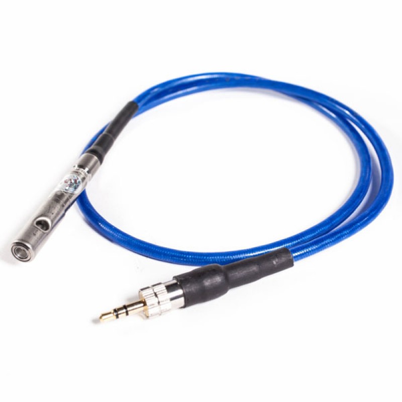
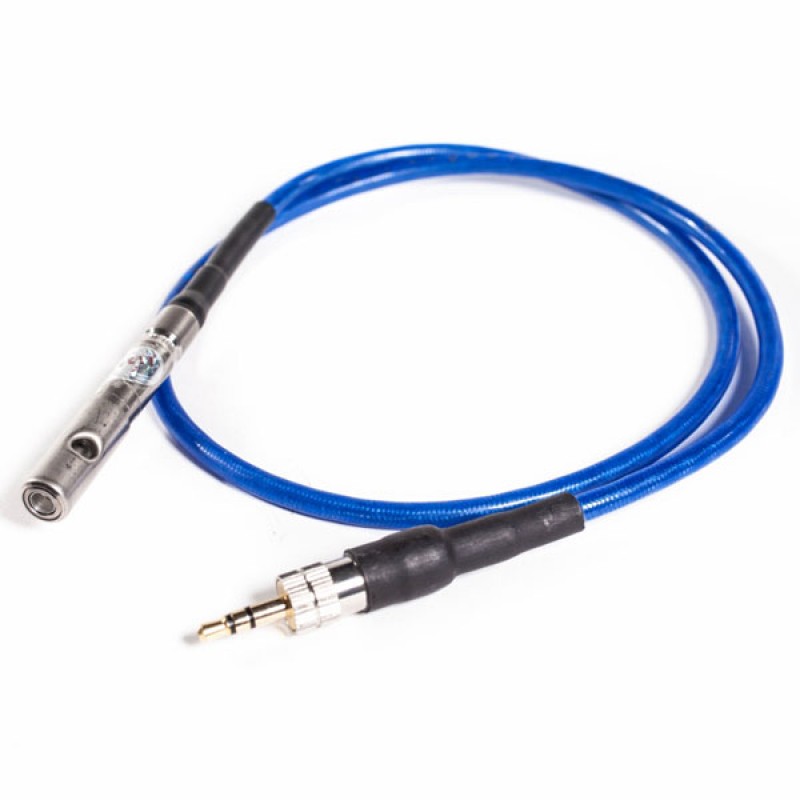

Vigil Cutter
€100.00
Technical Specifications.
| Specification | Details |
|---|---|
| Activation Time | < 20 milliseconds |
| Weight | 58 grams (approx.) |
| Material | Stainless steel and reinforced poly |
| Dimensions | 38mm x 15mm x 15mm |
| Connector Type | Plug-lock with retention clip |
| Certification | CE, ISO 9001:2015, EN 1651 |
| Operating Temperature | -30°C to +60°C |
| Storage Temperature | -40°C to +85°C |
| Shelf Life | 20 years |
| Maintenance | None required |
| Compatibility | Vigil Cuatro, 2+, 2, and earlier |
Vigil Cutter: Replacement Cutting Unit for Vigil Automatic Activation Devices
Understanding the Vigil Cutter and Its Role in a Parachute System
Parachute Jump Australia, Skydive Byron Bay and Cairns Skydiving
Whether a jumper participates in a parachute jump Australia operation, visits Skydive Byron Bay, or considers Cairns skydiving, the cutter must be installed in accordance with the equipment manufacturer’s approved configuration. Geographic location does not change the component’s purpose, although local regulations, reserve inspection cycles, rigger qualifications, and drop-zone requirements may differ.
Weight Limit Skydiving and System Configuration.
A weight limit skydiving policy usually relates to the complete harness, container, reserve, main canopy, aircraft, and operator—not the cutter by itself. The cutter should never be selected according to body weight or wing loading. Instead, the exact replacement must match the Vigil model, serial-number requirements, cutter configuration, and approved installation.
Parachute Rig, Skydiving Rig and Container Skydive Installation
Inside a compatible parachute rig or skydiving rig, the cutter sits in a dedicated elastic retainer. The reserve closing loop must pass directly through the cutter opening. If it does not, activation cannot sever the loop. The cutter’s precise position depends on the approved container skydive design and must follow the harness-and-container manufacturer’s instructions.
Skydiving Rigging, Linewear and Parts of a Parachute
Professional skydiving rigging is essential because the Vigil Cutter works within the reserve system. Routine linewear on the main canopy is a separate maintenance concern, while the parts of a parachute surrounding the cutter include the reserve closing loop, container flaps, grommets, pilot chute, freebag, reserve canopy, control unit, and processing unit.
How the Vigil Cutter Works
The cutter contains a confined circular cutting mechanism. When the processing unit sends the firing command, the pyrotechnic element drives the cutting action through the reserve loop. Because the cutting event remains confined inside the cutter assembly, the mechanism is designed to avoid direct damage to the surrounding parachute components.
Why Precise Loop Routing Is Important
Correct routing determines whether the component can perform its intended task. The reserve loop must pass through the cutter hole, and the cutter must sit in its approved retainer with the correct orientation. A misplaced cutter, incompatible loop, damaged cable, or incorrect installation could prevent proper operation.
Hook Blade Knife, Hook Knife Skydiving and Skydive Hook Knife
A hook blade knife, hook knife skydiving tool, or skydive hook knife is a manually operated emergency cutting tool. It is not interchangeable with the Vigil Cutter. The Vigil component responds electronically and acts only on the reserve closing loop within its approved system.
Fire Parachute and Cypress Fire Skydiving
The phrases fire parachute and cypress fire skydiving are sometimes used when discussing automatic activation. However, the Vigil Cutter belongs to the Vigil system, not CYPRES. Its internal pyrotechnic event is a controlled mechanical activation, not an open flame or uncontrolled fire.
Tracking Jump, Skydiving Speed and Speed Sky Diving
During a tracking jump, high skydiving speed, or speed sky diving, the cutter does not measure altitude or speed independently. The main processing unit evaluates pressure-derived altitude and vertical speed. The cutter acts only after receiving the activation signal.
Wingsuit Sport, Vector Wingsuit and Gliding Suit Wingsuit
The wingsuit sport, vector wingsuit, gliding suit wingsuit, skydiving gliding suit, fly suits, wing suits for sale, and price of wingsuit concern body-flight equipment. A wingsuit or supposed tandem wingsuit does not alter the cutter’s installation procedure. Mode selection and system configuration must still follow official Vigil instructions.
Base Jumping, Baseline Jumping and Base Canopy
Base jumping, sometimes incorrectly called baseline jumping, uses specialized equipment and procedures. A base canopy system may not include the same reserve-container arrangement as a conventional dual-parachute system. Therefore, the Vigil Cutter should never be installed outside an approved application.
Skydiving Helmet, Skydive Helmets and Full Face Skydiving Helmet
A skydiving helmet, skydive helmets, sky helmet skydiving model, sky diving helmet, or full face skydiving helmet does not connect to the cutter. Products such as the G35 helmet, Cookie G4 helmet, or another skydiving helmet full face design serve separate protective and equipment-mounting functions.
Best Skydiving Helmet, Skydiving Glasses and Skydiver Goggles
The best skydiving helmet depends on fit and intended use. Likewise, skydiving glasses, skydiver goggles, and the question can you wear glasses while skydiving relate to visibility and personal equipment rather than automatic reserve activation.
Skydiving Downsizing Chart, Smallest Canopy and Canopy Flight
A skydiving downsizing chart, the smallest canopy, and advanced canopy flight decisions do not determine cutter compatibility. High-performance equipment such as Fluid Wings, a Safire 3, or specialized landing flight risers requires separate training and evaluation.
Freefly Pud Handle, Gear Bag Skydive and Skydiving Equipment List
A freefly pud handle, gear bag skydive setup, and complete skydiving equipment list may include many components, but none should obstruct the reserve system or cutter cable. Only approved routing and installation should be accepted.
CRW Skydiving and Jumper Pilot Responsibilities
During CRW skydiving, both a canopy pilot and any jumper pilot must understand that an automatic activation device remains a backup. The Vigil Cutter does not replace altitude awareness, emergency procedures, deployment discipline, or sound decision-making.
Indoor Wingsuit, iFly Colorado Springs and Skydiving Tube
An indoor wingsuit facility, iFly Colorado Springs, or skydiving tube training environment does not require the cutter’s reserve-loop function. Those controlled facilities differ fundamentally from aircraft skydiving.
Skydive Belize, Skydiving Blue Hole Belize and New Skydive Locations
Travel searches such as Skydive Belize, skydiving Blue Hole Belize, or new skydive destinations should include local equipment-rule checks. A qualified rigger should verify the installation before the system is used after servicing or international travel.
Nude Parachute Jump, Skydiving Nude and #Skydiving Latest
A nude parachute jump, skydiving nude, #skydiving latest, or a general skydiving website does not describe the cutter’s technical function. The component should be evaluated through official documentation, traceable replacement parts, serial-number verification, and professional installation rather than unrelated online trends.
Design, Installation, Operation, and Maintenance
Precision Component Design
The cutting unit is a compact mechanical and electronic component developed for use within a compatible automatic activation system. Its role is highly specific: when it receives the correct activation signal, it severs the reserve closing loop so the reserve container can begin opening.
The housing protects the internal mechanism from normal handling and environmental exposure. However, it should still be treated as a sensitive life-support component. Crushing, bending, drilling, opening, modifying, or striking the housing may damage the internal assembly.
Its external appearance should never be used as the only measure of serviceability. Internal damage may exist even when the casing appears normal. Therefore, any unit exposed to severe impact, moisture, chemical contamination, or excessive heat should be examined by a qualified technician.
How the Cutting Mechanism Operates
The component remains inactive during normal operation. It does not continuously cut, move, or apply pressure to the reserve closing loop.
When the processing unit detects the programmed activation conditions, an electrical command is sent through the cable. The internal mechanism then drives a cutting element through the loop material.
This action is designed to occur rapidly. Once the loop has been severed, tension holding the reserve container closed is released. The spring-loaded pilot chute can then begin the extraction sequence.
The cutting action is only one stage of reserve deployment. The pilot chute, bridle, freebag, lines, and reserve canopy must still function correctly afterward.
Why Installation Accuracy Matters
Correct installation is essential because the loop must pass directly through the cutting opening. If the loop is routed beside the opening rather than through it, the mechanism cannot perform its intended function.
The housing must also sit in the position approved by the harness-and-container manufacturer. Incorrect placement may affect container closing, cable routing, reserve pilot-chute movement, or access during maintenance.
Installation accuracy includes:
- Correct orientation
- Proper loop routing
- Secure housing placement
- Suitable cable positioning
- Compatible loop material
- Correct connector engagement
- Adequate clearance from moving parts
Each point should be verified before the reserve container is closed.
Compatible Closing Loops
Only approved reserve closing-loop materials should be used. The loop must have the correct diameter, construction, condition, and length for the installed system.
A loop that is too thick may require excessive cutting force. Meanwhile, a loop that is too thin, damaged, contaminated, or incorrectly prepared may reduce reserve-container security.
The loop should be replaced whenever wear, flattening, heat damage, broken fibers, discoloration, chemical exposure, or excessive friction is observed.
The cutting opening should never be enlarged or altered to accommodate an unsuitable loop.
Electrical Connection
The cable provides the communication path between the processing system and the cutting mechanism. Therefore, the connector must remain fully seated and protected from contamination.
A loose connection may prevent the activation command from reaching the component. However, forcing a connector into place can also damage pins, insulation, or locking features.
The connection area should remain dry and clean. Oil, dirt, moisture, corrosion, and foreign material may interfere with electrical contact.
The cable should be routed with smooth curves rather than sharp bends. Excessive tension, repeated folding, or compression under container hardware should be avoided.
Reserve Container Integration
The cutting mechanism functions within a larger reserve system. Its installation must not interfere with the reserve pilot chute, bridle, freebag, flap sequence, or internal packing arrangement.
The reserve container should close with the expected tension. Excessive closing pressure may indicate that the packed volume, loop length, component placement, or internal arrangement is unsuitable.
No part of the cable should cross an area where it may become trapped during opening. Likewise, the housing should not press against grommets, metal edges, or structural seams.
A complete functional and visual inspection should be performed before the system is returned to service.
Operating Conditions
The component is designed to remain inactive until a valid firing command is received. Normal aircraft ascent, routine movement, packing pressure, and ordinary handling should not cause activation.
Nevertheless, the complete system must be configured correctly. An unsuitable operating mode or incorrect altitude reference may cause the processing unit to interpret conditions differently from what the user expects.
The cutting unit itself does not measure altitude, calculate vertical speed, or determine whether an emergency exists. Those functions belong to the processing electronics.
Single-Use Operation
Once the mechanism has fired, the component must be replaced. It cannot be reset, repaired, rearmed, or reused.
An activated unit may contain a severed loop fragment or visible evidence of internal movement. However, users should not attempt to inspect the internal mechanism by opening the housing.
The replacement process should include a complete reserve-system inspection. The cause of activation should also be reviewed before the equipment is returned to service.
Pre-Installation Inspection
Before installation, the replacement component should be checked carefully.
The inspection should confirm:
- Correct model compatibility
- Undamaged packaging
- Clean housing
- Intact cable insulation
- Secure connector
- No corrosion
- No dents or cracks
- No signs of previous activation
- Traceable manufacturing information
A replacement part with uncertain origin or missing identification should not be installed.
Routine Inspection
Routine inspection normally occurs during reserve servicing or whenever the system has been disturbed.
The technician should confirm that the housing remains secure and that the loop passes correctly through the cutting opening. Cable routing should also be checked for compression, abrasion, twisting, or sharp bends.
The unit should remain free from contamination. Dust, sand, oil, moisture, and packing debris should not be allowed to collect around the mechanism or connector.
Any unusual condition should be resolved before the reserve container is closed.
Moisture Exposure
Moisture may affect electrical connections, cable insulation, metal surfaces, and surrounding parachute materials.
If the system becomes wet, it should be removed from service and inspected. The equipment should be dried naturally in a clean, ventilated environment.
Hair dryers, heaters, ovens, open flames, and other direct heat sources should not be used. Excessive heat may damage electronic parts, coatings, fabric, and structural materials.
Water exposure should always be documented for future maintenance reference.
Impact and Compression Damage
A severe impact may damage the internal mechanism even when no external crack is visible. Compression may also deform the housing or affect the cable connection.
Equipment that has been dropped from height, crushed during transport, involved in an aircraft incident, or exposed to heavy loading should be inspected professionally.
The user should not continue using the system simply because it powers on. Electronic communication does not prove that the mechanical cutting action remains reliable.
Storage Requirements
The system should be stored in a cool, dry, and secure environment.
It should be protected from:
- Direct sunlight
- Excessive heat
- Freezing moisture
- Fuel and oil
- Cleaning chemicals
- Battery leakage
- Sharp tools
- Heavy objects
- Unauthorized handling
Long-term storage records should include the date, environmental conditions, and any maintenance completed before storage.
Cleaning Guidance
The exterior should only be cleaned according to approved maintenance procedures.
Strong solvents, lubricants, abrasive materials, compressed air, and household cleaning products should not be applied. These substances may damage seals, insulation, markings, or internal components.
Loose surface dust may be removed gently during professional servicing. The housing should never be submerged in water.
Troubleshooting Procedures
When the control unit displays a fault, the system should be removed from operational use until the cause is identified.
Possible causes may include:
- Weak power supply
- Damaged cable
- Loose connector
- Internal electronic fault
- Activated mechanism
- Moisture contamination
- Incorrect installation
- Processing-unit malfunction
Users should not attempt to test the cutting action manually. Diagnostic procedures must follow the official service guidance.
Professional Servicing
Life-support equipment requires competent servicing. Replacement, installation, reserve closing, and compatibility decisions should be handled by an appropriately qualified professional.
The technician should record the part identification, installation date, reserve-service date, and reason for replacement.
Professional servicing helps ensure that the component works as part of the complete reserve deployment system rather than as an isolated device.
Importance of Documentation
Accurate records improve traceability and maintenance quality.
Useful information includes:
- Component identification
- System serial number
- Installation date
- Activation history
- Exposure to water or impact
- Previous repairs
- Inspection findings
- Replacement reason
- Technician details
These records may become important during troubleshooting, resale, regulatory inspection, or manufacturer support.
Safety Responsibility
The cutting mechanism is an emergency backup component. It does not replace altitude awareness, manual deployment, emergency procedures, training, or responsible decision-making.
Reliable operation depends on correct installation, approved materials, compatible equipment, careful maintenance, proper configuration, and professional inspection.
The user should always understand that no mechanical or electronic system can eliminate every risk associated with parachuting.
Inspection, Replacement, Storage, Troubleshooting, and Safety Responsibilities
Pre-Use Inspection
Before the equipment is placed into service, the complete automatic activation system should be inspected according to the manufacturer’s instructions. The cutting unit, cable, connector, processing unit, display, reserve closing loop, and installation position should all be checked.
The cutting unit should sit securely in its approved holder. It should not move freely, press against sharp hardware, or create unusual tension on the cable. In addition, the reserve closing loop must pass correctly through the cutting opening.
Any visible damage requires professional evaluation. Warning signs may include:
- Cracks or dents in the housing
- A bent or distorted opening
- Damaged cable insulation
- Loose electrical connections
- Corrosion or contamination
- Evidence of moisture exposure
- Heat damage
- An activated cutting mechanism
- Incorrect positioning inside the reserve container
The system should not be used when its condition is uncertain.
When Replacement Is Required
The cutting unit must be replaced after activation because it is a single-use component. It cannot be reset, reloaded, or repaired for repeated operation.
Replacement may also be necessary when physical damage, electrical faults, cable deterioration, corrosion, or incompatible installation is discovered. A component that has experienced a severe impact, water exposure, chemical contamination, or excessive heat should be examined before continued use.
Only the correct replacement component should be installed. Similar appearance does not confirm compatibility. The model, connector type, cable length, system generation, and manufacturer instructions must all be considered.
Professional Installation
Replacement should be performed only by an appropriately qualified professional. The reserve container must normally be opened, and the closing system must be reassembled correctly after the work has been completed.
During installation, the technician should verify that:
- The correct component has been supplied
- The electrical connection is secure
- The cable is routed without sharp bends
- The housing sits in the approved location
- The reserve closing loop passes through the opening
- The cable cannot interfere with the reserve pilot chute
- No component is trapped between container flaps
- The reserve system closes within approved limits
Improvised routing should never be accepted. Even a functional electronic connection may be ineffective when the mechanical installation is incorrect.
Understanding the Activation Sequence
The cutting unit does not decide when activation should occur. The processing system evaluates altitude, descent rate, selected operating mode, and other programmed conditions.
When those conditions are met, an electronic firing command is sent to the cutting unit. The mechanism then severs the reserve closing loop. After the loop is cut, the reserve container can open through the force of the spring-loaded pilot chute.
Several actions must still occur after the cut. The container flaps must release, the pilot chute must launch, the freebag must extract, and the reserve canopy must deploy and inflate.
Therefore, successful cutting is only one part of a larger emergency deployment sequence.
System Limitations
The component provides an important backup function, but it cannot guarantee survival or complete reserve deployment.
It cannot:
- Correct an incorrectly packed reserve
- Detect every dangerous situation
- Replace manual emergency procedures
- Prevent entanglement
- Repair damaged equipment
- Select a safe landing area
- Confirm that sufficient altitude remains
- Compensate for an unsuitable operating mode
- Guarantee canopy inflation
Users should understand these limitations before relying on the system.
Troubleshooting a Warning or Error
When the control unit shows an error, the entire system should be removed from operational use until the cause has been identified.
The problem may involve the battery, processing unit, display, electrical connector, cable, or cutting unit. However, users should not attempt to bypass an error or test the cutting mechanism manually.
The following information can help a technician assess the problem:
- The displayed error code
- The system serial number
- The operating mode selected
- The date of the last inspection
- Recent reserve work
- Any impact or moisture exposure
- Battery condition
- Whether the component has previously activated
The manufacturer’s diagnostic procedure should be followed carefully.
Cable Protection
The cable carries the activation signal and should be protected from pressure, stretching, twisting, and repeated bending.
A sharply folded cable may develop internal damage even when the outer covering appears normal. Similarly, an incorrectly routed cable may become trapped during closing or damaged when the reserve pilot chute launches.
The cable should follow the approved path and remain clear of moving parts, metal edges, closing flaps, and packed fabric.
Storage Conditions
The complete system should be stored in a clean, dry, and temperature-controlled environment.
Excessive heat may damage electronic parts, batteries, cables, and surrounding parachute materials. Moisture may cause corrosion or electrical problems. Therefore, the equipment should not be left in a hot vehicle, damp room, flooded storage area, or near industrial chemicals.
Direct sunlight should also be avoided during long-term storage. Although the cutting unit remains inside the container, the complete system may still be affected by heat and ultraviolet exposure.
Air Travel and Transportation
During transportation, the equipment should be protected from crushing, severe impact, and unauthorized handling.
Airport security personnel may ask about electronic or pyrotechnic components. Owners should carry the appropriate manufacturer documentation when traveling.
The system should not be removed, disconnected, or altered solely to satisfy an unofficial request without consulting a qualified professional. After any inspection that involves opening or disturbing the reserve container, the equipment should be checked before use.
After an Activation
After activation, the equipment should be handled as an emergency system that requires full inspection.
The activated component must be replaced. In addition, the reserve container, reserve closing loop, pilot chute, freebag, reserve canopy, cable routing, and electronic system should be examined.
The event should also be reviewed to determine why activation occurred. Possible reasons may include delayed deployment, high-speed descent, an emergency, incorrect mode selection, aircraft descent, or another operational factor.
Understanding the event can help prevent future problems.
Recordkeeping
Owners and equipment managers should maintain accurate records of inspections, reserve packing, activation events, replacement dates, repairs, and unusual system behavior.
These records help technicians evaluate the history of the system. They may also support resale, maintenance planning, and regulatory compliance.
The component’s identity should remain traceable through its packaging, service documents, and installation records.
Responsible Use
An automatic activation system should be treated as a final backup rather than a substitute for awareness and training.
The user must still monitor altitude, deploy the main parachute at the planned height, recognize malfunctions, and perform emergency procedures when required.
Reliable performance depends on correct installation, compatible equipment, proper configuration, regular inspection, responsible storage, and professional maintenance.
Service Life, Replacement Decisions, Compatibility, and Long-Term Reliability
Understanding Service Life
The cutting unit forms part of a larger electronic safety system. Its usable service life depends on the approved lifespan of that complete system, its condition, installation history, and manufacturer guidance.
Owners should never assume that a component remains suitable indefinitely simply because it has not activated. Age, moisture, impact, cable stress, contamination, and improper storage can affect reliability.
The equipment records should show when the component was installed, whether it has been moved between systems, and whether it has experienced unusual environmental conditions. When its history cannot be confirmed, a qualified technician should evaluate it before further use.
Reasons for Replacement
Activation is the clearest reason for replacement because the mechanism is designed for one cutting event. After firing, the unit cannot be reset or reused.
Replacement may also be required when an inspection reveals physical damage, cable deterioration, connector problems, corrosion, contamination, or uncertain compatibility.
Other possible reasons include:
- An unexplained system error
- Damage caused by an impact
- Water or chemical exposure
- Severe compression during transport
- Missing identification markings
- Uncertain maintenance history
- An incompatible connector
- A manufacturer service notice
- An installation change
A functioning display does not prove that every internal component remains serviceable. Therefore, the complete system should be assessed rather than checking only whether it powers on.
Choosing the Correct Replacement
The replacement component must match the exact system configuration. Visual similarity alone is not sufficient.
Different generations may use different connectors, cable lengths, installation positions, or technical requirements. Consequently, the system model, serial number, manufacturing information, and official compatibility guidance should be checked before purchase.
A genuine replacement should arrive with clear identification and traceable packaging. Missing labels, altered connectors, damaged cables, or uncertain origin should be treated as warning signs.
Used components should be approached cautiously because their activation status, storage history, and internal condition may be difficult to verify.
Installation After Replacement
After the new unit has been connected, the technician should inspect the complete installation before closing the reserve container.
The housing must sit securely in its designated location. The cable should follow the approved route, while the closing loop should pass directly through the cutting opening.
The technician should also confirm that the cable does not cross the pilot chute, bridle, freebag, flap edges, or other moving components.
Once the reserve has been packed and closed, the system should complete its normal startup and self-check sequence without displaying an error.
Why a Complete System Check Matters
Replacing one component does not automatically confirm that the surrounding equipment is ready for service.
The reserve closing loop may have been damaged during activation. The pilot chute, freebag, container flaps, grommets, cable routing, and electronic connections may also require inspection.
Furthermore, the cause of the activation should be identified. An event may result from a genuine emergency, delayed deployment, incorrect operating mode, unusual aircraft descent, or another condition.
Understanding the cause helps determine whether additional maintenance, training, or configuration changes are necessary.
Compatibility With the Reserve Closing System
The cutting mechanism works only when the closing system has been assembled correctly. The loop material, diameter, length, routing, and condition must meet the approved requirements.
A loop that is excessively worn may fail before intended use. Conversely, one that is too thick or made from unsuitable material may not respond as expected.
The closing loop should move cleanly through the container grommets without unnecessary friction. Rough edges, damaged grommets, contamination, or incorrect routing may interfere with normal container opening.
Only approved materials should be installed.
Be the first to review “Vigil Cutter”
Related products


Reviews
There are no reviews yet.